Microwave Plasma Chamber – Part 2 – RF Energy Shielding Primer

RF Shielding Primer

There’s a lot of in-depth overview random basic RF information. With that said I don’t mind getting into the details because this information will help keep me safe while I perform experiments in the future.
Magnetron
Magnetron

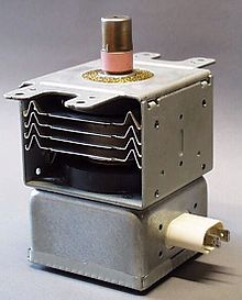
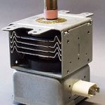
A magnetron generates large amounts of RF energy and emits that energy as an antenna pumped through a wave guide. Most microwaves transmit/operate at 2.45GHz. Unless something is wrong with your microwave or you have taken it apart like I will be doing the RF energy, 2.45GHz, transmission is contained within your microwave using a Faraday cage. On your right is an example of a crude Faraday cage. While crude this mesh size would probably be safe to use for 2.4GHz.
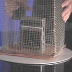
Photo from www.physics.montana.edu
Radio in a Faraday Cage photo from http://www.physics.montana.edu/demonstrations/video/5_electricityandmagnetism/demos/radioinfaradaycage.html

A microwave oven works by pumping a lot of RF energy into an enclosure where it bombards the molecules of food or whatever you have put in your microwave. This RF energy is not in a straight line but is guided through a wave guide then and then bounced off the metal walls of the inside of the microwave. The RF energy then vibrates the molecules which creates heat. This is like when you rub your hands together (friction) and they get warm but on a molecular level. What I don’t want is my molecules to get vibrated.

The Faraday cage is made up of the mesh in the window as well as the metal case which share a chassis ground. The mesh in the window blocks the the RF because the mesh size is smaller than the wavelength of 2.45GHz/2450MHz/2450000000Hz. If the mesh size is lower than the nominal wavelength the mesh should be effective. Look at the list below to see what the wavelengths in size is. For this project I plan on using the RF blocking glass that I obtained samples of from Viracon which is way different than a Faraday cage but same principle. You can see the article I linked to but I also included an image here.

  • Full Wavelength = 12.23643cm/122.3643mm = 0.1223643m
  • Half Wavelength = 6.118215cm/61.18215mm
  • Quarter Wavelength = 3.0591cm/30.591075mm

You can calculate the wavelength using the formula ? = c/? or 0.1223640816326531 = 299792000/2450000000

? = frequency in hz, = speed of light in mps 299792000, = Wavelength in meters

N5JLC is my math right?

So basically if my mesh is smaller than 30mm, if I’m right, I should be protected. I plan to use the glass but if needed I will use hardware cloth.

RF Meters

In order to protect myself and nearby electronics I want to monitor external and internal RF to ensure there is not leakage. RF Meters in general are not that difficult to build but ones that cover the 2.4GHz range require a bit more than a germanium diode and multimeter. In short you’ll probably see a 2.4GHz RF Meter project coming soon. Below are some RF Meter projects but if you know of any please let me know.

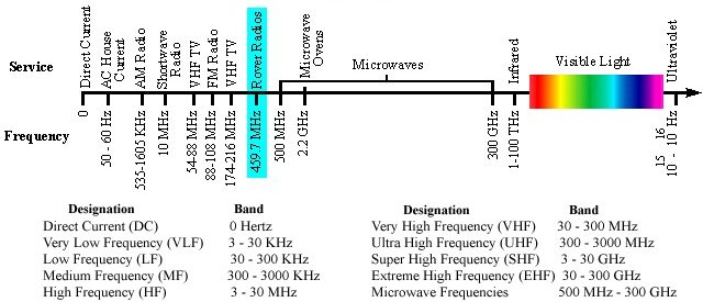
Frequency Spectrum Chart

Frequency Spectrum

Symbols and Values

  • ? = frequency in hz
  • c = speed of light in meters per second (mps) 299792000
  • ? = Wavelength in meters

Microwave Plasma Chamber – Part 1 – The Plan


Microwave Plasma Chamber – Part 1 – The Plan
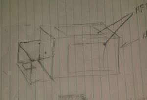
Normally I throw together a project with rough notes, research along the way, then after half attempts/failures I get around to cooking that down to a post on here. This time you will get everything. With this project I will be posting my ideas, planning, results of research and the project in stages. Here’s my initial idea written out and some really rough ideas thrown on paper. This has been a project I’ve been wanting to do for some time now and have been talking about it forever.

Roughed together a drawing of my ideas and what I think will work for this project. No measurements in mind while throwing ideas on paper.

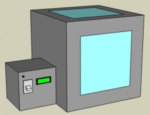
What I want is a chamber with viewing windows to see the plasma when it’s created. In addition to the view windows and enclosure I will need a power supply to drive this thing.


Took my drawing and opened SketchUp with considerations for what measurements I do have. As I type this staring at my digital drawing already considering separating the power supply making it usable for other projects in the future. It would be cool to have a high voltage isolation transformer for things like a Jacobs Ladder or an arc furnace.

Regardless of the power supply what I have in mind here is the plasma chamber with viewing windows which are 12 inches square. I plan to have a microcontroller monitor and remotely turn on or more importantly off the chamber.


The main chamber will have the magnetron from a microwave mounted inside of it with a metal housing around it and it’s electronics to protect them. The antenna portion of the magnetron will rest inside a waveguide (horn) that points at the center of the chamber. This directed energy will excite particles creating plasma. I probably need to consider a way to draw a vacuum inside the chamber for later experiments.

I plan to use parts of the original microwave casing and sheet metal for the housing. If I need more material I might scrap old PC cases. To help minimize RF leakage I am considering using aluminum duct tape and angled aluminum.

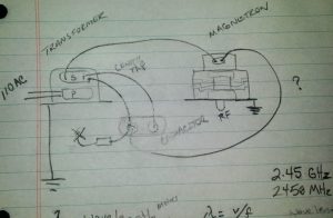
Magnetron Wiring

Need to look at the manufacturer specifications and double check my work but I think this how the magnetron wiring is done minus the existing controls.

PreRelease Late Night EditRemember how I said I’d share everything? Well do you see where on the capacitor I have an element leading to an X? I think I already screwed up and that is supposed to be a diode going to chassis ground. 

I also have this crazy idea in the back of my head thinking of using pulse width modulation to have greater control of the RF output. That may be total non-sense but the implications could maybe be cool.

RF meters will be needed to monitor interior and exterior RF levels. I plan to build at least 2 of them and will post that project soon. I will post more about the RF energy in my next post of this project.

Click here to browse through posts written about my interests in Microwave Projects

Microwave Deathray

Magnetron
There is something called a Magnetron, not to be confused with Megatron,  inside your microwave. This is the primary component that vibrates the molecules of what you are heating in your microwave to generate heat. Mmmm in the words of Jim Gaffigan Haaaot Pocket!

Ok so it’s not necessarily a death ray but I wouldn’t want to put my junk in front of one. Ever heard of a herf gun? A herf gun is a directed energy weapon. Boeing’s CHAMP recently put on a show taking out targeted computers using one. Supposedly a crude herf gun can be built attaching a waveguide or horn antenna to the output of the magnetron.

Original video was pulled from Youtube updated 7/10/2016

https://www.youtube.com/watch?v=0mjua2e8Y7k

Someone else’s crazy project

Note from wiki “a 1.1 kilowatt input will generally create about 700 watts of microwave power”

What I’d like to do

  • Build a Faraday cage so that I can safely perform testing
  • Get one of these powered up with an inline dimmer switch so that I can control the output
  • Build a horn antenna to attach to the Magnetron so that I can control the direction of output
  • Use some equipment to measure the emitted power with in controlled area
  • Use a frequency counter to get a reading of what range is play
  • Cook food from a distance
  • Light up bulbs in a field
  • Destroy some electronics

Related Projects on Instructables

[phpInstrucatblesKeyword]keyword-plasma/keyword-microwave[/phpInstrucatblesKeyword]

Click here to browse through posts written about my interests in Microwave Projects

Top