Microwave Plasma Chamber – Part 1 – The Plan

Normally I throw together a project with rough notes, research along the way, then after half attempts/failures I get around to cooking that down to a post on here. This time you will get everything. With this project I will be posting my ideas, planning, results of research and the project in stages. Here’s my initial idea written out and some really rough ideas thrown on paper. This has been a project I’ve been wanting to do for some time now and have been talking about it forever.
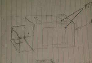
Roughed together a drawing of my ideas and what I think will work for this project. No measurements in mind while throwing ideas on paper.

What I want is a chamber with viewing windows to see the plasma when it’s created. In addition to the view windows and enclosure I will need a power supply to drive this thing.


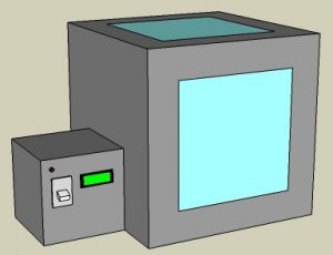
Took my drawing and opened SketchUp with considerations for what measurements I do have. As I type this staring at my digital drawing already considering separating the power supply making it usable for other projects in the future. It would be cool to have a high voltage isolation transformer for things like a Jacobs Ladder or an arc furnace.

Regardless of the power supply what I have in mind here is the plasma chamber with viewing windows which are 12 inches square. I plan to have a microcontroller monitor and remotely turn on or more importantly off the chamber.


The main chamber will have the magnetron from a microwave mounted inside of it with a metal housing around it and it’s electronics to protect them. The antenna portion of the magnetron will rest inside a waveguide (horn) that points at the center of the chamber. This directed energy will excite particles creating plasma. I probably need to consider a way to draw a vacuum inside the chamber for later experiments.

I plan to use parts of the original microwave casing and sheet metal for the housing. If I need more material I might scrap old PC cases. To help minimize RF leakage I am considering using aluminum duct tape and angled aluminum.

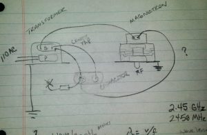
Magnetron Wiring

Need to look at the manufacturer specifications and double check my work but I think this how the magnetron wiring is done minus the existing controls.

PreRelease Late Night EditRemember how I said I’d share everything? Well do you see where on the capacitor I have an element leading to an X? I think I already screwed up and that is supposed to be a diode going to chassis ground. 

I also have this crazy idea in the back of my head thinking of using pulse width modulation to have greater control of the RF output. That may be total non-sense but the implications could maybe be cool.

RF meters will be needed to monitor interior and exterior RF levels. I plan to build at least 2 of them and will post that project soon. I will post more about the RF energy in my next post of this project.

Click here to browse through posts written about my interests in Microwave Projects

Creating Plasma in a Microwave

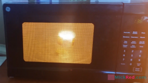
Plasma PreviewAfter speaking with John Cohn and hearing about this experiment I just had to try it. Video recording is rough but you’ll get the idea. Soon I will be ramping this up when I start my series of microwave oven experiments where we will build everything from a high voltage power supply to a smelter and maybe just maybe a Microwave Death Ray (ok maybe just a herf gun).

Don’t try this at home!

Click here to browse through posts written about my interests in Microwave Projects
RedBeards Lab Gets New Equipment

Is that a pile of junk? That is a gold mine for this guy. New equipment for the RedBeard lab. I have no idea if any of this stuff works except the centrifuge which does very well.

My son has an interest in becoming a Genetic Engineer so I told him well I don’t know much about that subject but I will learn enough to get you started. After reaching out to friends I got this equipment donated to the lab.

Some of this equipment is old but what better way to learn. Lets see if we can wire some of this stuff to a Raspberry Pi or Arduino, re-purpose it, hack it and/or learn from it.

  • Spectrometer
  • Gas Chromatograph
  • Electrophoresis Power Supply
  • Centrifuge


Projects for 2016

Happy New Years Everyone!!!

Here’s a preview of a few projects that I have planned for this year.

Automated AeroGarden

An automated AeroGarden based hydroponic-ish herb garden. I picked up this AeroGarden version 3 at a resale shop for about $8. I took it apart, cleaned it up, tested the unit and found it to be in working order. I need to replace the tubing and filter but all in all that’s a good find. I will be doing this project in stages. First will be 3d printing the planter cartridges that hold the sponge and just get the unit functioning. 2nd will be automating a few functions using an Arduino and holding tanks for nutrients and reserve water.

AeroGarden

Time-lapse Camera

An Arduino based Time-lapse Camera. This will be used in production of Dared to Survive shows.

Game Camera

An Arduino based Game Camera that will also collect environmental information such as Temperature, Humidity, etc. The data will be stored on an SD-Card and will be later used in an app to develop forecasting predictions.

Passive Repeater

I want to attempt a few things with a Passive Repeater design that integrates simple bi-directional amplification and/or filters.

Bench Top Power Supply

A simple bench top power supply made from PC and Server power supplies.

More Podcasts

I plan on starting a weekly 15 min per episode podcast covering my top 5 favorite Instructables projects.

I’m sure this list will change throughout the year so stay tuned. Have project suggestions or requests? Reach out to me @Mr_Red_Beard  on Twitter.

Philips TV Model 37mf331d/37 Power Supply Repair

Philips TV Model 37mf331d/37
2006 – 37” LCD TV with Fluorescent Backlight
Information on TV

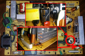
Got a call about this Philips TV and was asked if I could fix it. When I went to check it out the TV was already taken apart and the owner had already researched the issue identifying the power supply as the culprit. At first look I saw that he was right because there was a section blown out to include an erupted capacitor. So I left with a part number of and the power supply.

715t2056-1 Issues Identified
715t2056-1 Issues Identified  

Power Supply Unit: 715t2056-1

This the same power supply used in several products so I thought if nothing else I might be able to salvage an old power supply board from something else. Its more fun to try and fix the issue so I was hoping salvage wouldn’t be the solution. I ordered the surface mounted resistor, zener diode and capacitor from Mouser for less than $2.

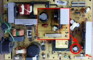
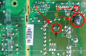
I removed and replaced the capacitor with no issues. Then I began to remove the diode and the damage really reared its head. Whenever these parts blew it blew a chunk of circuit board with it that wasn’t noticeable until the solder was taken off. This took off the surface mounted resistor and the mounting location for one side of the diode. Well crap! After giving this some thought I came to the conclusion that the resistor was probably more for tolerance matching and protection than anything else so I refilled the broken trace and connected the diode directly to it. This was a bit sloppy due to the missing pieces of circuit board so I covered the area with hot glue to secure it.

715t2056-1 New Part Installed Top
715t2056-1 New Part Installed Bottom

A. Capacitor  B. Diode Connection  C. Repaired Broken Trace, Bypassed Resistor & Diode Connection

Not being able to test it immediately after repair made me a bit worried. Today I went back and installed the repaired power supply and reassembled the TV just enough to test it out. When we plugged it in I could hear it hum to life automatically. Initially it did nothing but light up the power button but after a few seconds the screen came on and this older flat-screen TV got an extended life for less than two dollars.

Top