Microwave Plasma Chamber – Part 3 – What is Plasma? Experiments planned

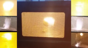
Photos of plasma being created in a microwave oven from 2 experiments I conducted in the past

Most people are familiar with 3 states of matter being solid, liquid, and gas but a lot of people are not familiar with the 4th. The fourth state of matter is plasma defined as an ionized gaseous mixture consisting of highly charged positive ions and free electrons (negative charge) that result in little or no electric charge. The amount of energy in each state of matter increases as you progress. Plasma is typically created at low pressures or at very high temperatures. Believe it or not plasma is the most common form of matter in the universe. [taken from definition, wiki, and general knowledge]

Examples of plasma are neon signs, CFL bulbs, lightning strikes and probably what I’m most interested in Fusion (the sun). Uses of plasma can be found in the manufacturing of electronic components such as semiconductors, metal plating of glass/silicon/etc, mineral extraction, ion propulsion and one day a very clean and efficient energy source.

Plasma conducts electricity and can be manipulated with a magnetic field. These properties are at the core of what I want to accomplish with the plasma chamber.

Experiments for the chamber

  • Small scale plasma accelerator
  • Plasma sputter plating of metals on to glass
  • Ion drive simulation
  • Magnetic containment fields
  • Effect of plasma being pushed through a coil
  • Plasma being formed with various gases and/or particle filled gases
  • Custom waveguide antennas to concentrate energy for various applications
  • Effect of electricity being applied across plasma
  • Effect of shooting electrons through plasma
  • Find a way to manipulate power and frequency of RF signal


Microwave Plasma Chamber Part 1 & Part 2

Click here to browse through posts written about my interests in Microwave Projects

Microwave Plasma Chamber – Part 1 – The Plan

Normally I throw together a project with rough notes, research along the way, then after half attempts/failures I get around to cooking that down to a post on here. This time you will get everything. With this project I will be posting my ideas, planning, results of research and the project in stages. Here’s my initial idea written out and some really rough ideas thrown on paper. This has been a project I’ve been wanting to do for some time now and have been talking about it forever.

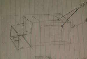
Roughed together a drawing of my ideas and what I think will work for this project. No measurements in mind while throwing ideas on paper.

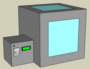
What I want is a chamber with viewing windows to see the plasma when it’s created. In addition to the view windows and enclosure I will need a power supply to drive this thing.


Took my drawing and opened SketchUp with considerations for what measurements I do have. As I type this staring at my digital drawing already considering separating the power supply making it usable for other projects in the future. It would be cool to have a high voltage isolation transformer for things like a Jacobs Ladder or an arc furnace.

Regardless of the power supply what I have in mind here is the plasma chamber with viewing windows which are 12 inches square. I plan to have a microcontroller monitor and remotely turn on or more importantly off the chamber.


The main chamber will have the magnetron from a microwave mounted inside of it with a metal housing around it and it’s electronics to protect them. The antenna portion of the magnetron will rest inside a waveguide (horn) that points at the center of the chamber. This directed energy will excite particles creating plasma. I probably need to consider a way to draw a vacuum inside the chamber for later experiments.

I plan to use parts of the original microwave casing and sheet metal for the housing. If I need more material I might scrap old PC cases. To help minimize RF leakage I am considering using aluminum duct tape and angled aluminum.

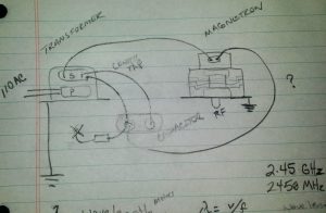
Magnetron Wiring

Need to look at the manufacturer specifications and double check my work but I think this how the magnetron wiring is done minus the existing controls.

PreRelease Late Night EditRemember how I said I’d share everything? Well do you see where on the capacitor I have an element leading to an X? I think I already screwed up and that is supposed to be a diode going to chassis ground. 

I also have this crazy idea in the back of my head thinking of using pulse width modulation to have greater control of the RF output. That may be total non-sense but the implications could maybe be cool.

RF meters will be needed to monitor interior and exterior RF levels. I plan to build at least 2 of them and will post that project soon. I will post more about the RF energy in my next post of this project.

Click here to browse through posts written about my interests in Microwave Projects
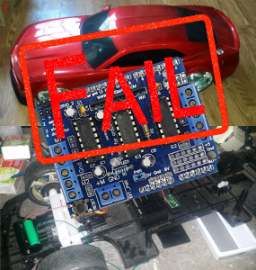
SainSmart L293D Fail!!

This is a project in the works but what the hey here’s sort of a preview. The plan is to use 2x 400MHz transceivers via 2x arduinos to control the motors on this RC car. I’ve already taken the original controller board out of the car and made room for the new components.

So I was sitting here setting up a SainSmart L293D Motor Driver using specs and guidance from Adafruit and either I missed something or the information is wrong. At 3.5vdc it works but could be pushed so I grabbed an 18vdc drill battery thinking it would be fine because the circuit as quoted from Adafruit below states that it is rated to 25vdc.

25vdc my foot cause as soon as I set it up smoke popped and I smell burning on both the arduino and motor controller. It still seems to work but surely problems will rear their head.

Just ordered better motor controllers (same as the one used in my R2D2) and 18650 battery holders. Wouldn’t be so bad but I think the arduino board is fried.

Just so anyone else is aware this is the link I purchased my L293D from on Amazon. I already complained but I’m not the first to do so.

4 H-Bridges: L293D chipset provides 0.6A per bridge (1.2A peak) with thermal shutdown protection, 4.5V to 25V

https://learn.adafruit.com/adafruit-motor-shield/overview

Top