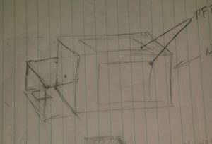
Normally I throw together a project with rough notes, research along the way, then after half attempts/failures I get around to cooking that down to a post on here. This time you will get everything. With this project I will be posting my ideas, planning, results of research and the project in stages. Here’s my initial idea written out and some really rough ideas thrown on paper. This has been a project I’ve been wanting to do for some time now and have been talking about it forever.

Roughed together a drawing of my ideas and what I think will work for this project. No measurements in mind while throwing ideas on paper.
What I want is a chamber with viewing windows to see the plasma when it’s created. In addition to the view windows and enclosure I will need a power supply to drive this thing.
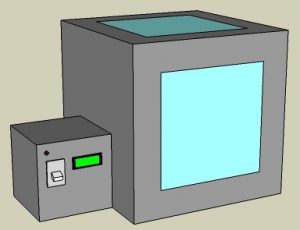
Took my drawing and opened SketchUp with considerations for what measurements I do have. As I type this staring at my digital drawing already considering separating the power supply making it usable for other projects in the future. It would be cool to have a high voltage isolation transformer for things like a Jacobs Ladder or an arc furnace.
Regardless of the power supply what I have in mind here is the plasma chamber with viewing windows which are 12 inches square. I plan to have a microcontroller monitor and remotely turn on or more importantly off the chamber.
The main chamber will have the magnetron from a microwave mounted inside of it with a metal housing around it and it’s electronics to protect them. The antenna portion of the magnetron will rest inside a waveguide (horn) that points at the center of the chamber. This directed energy will excite particles creating plasma. I probably need to consider a way to draw a vacuum inside the chamber for later experiments.
I plan to use parts of the original microwave casing and sheet metal for the housing. If I need more material I might scrap old PC cases. To help minimize RF leakage I am considering using aluminum duct tape and angled aluminum.
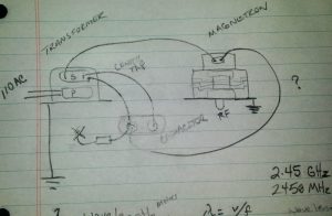
Need to look at the manufacturer specifications and double check my work but I think this how the magnetron wiring is done minus the existing controls.
PreRelease Late Night Edit – Remember how I said I’d share everything? Well do you see where on the capacitor I have an element leading to an X? I think I already screwed up and that is supposed to be a diode going to chassis ground.
I also have this crazy idea in the back of my head thinking of using pulse width modulation to have greater control of the RF output. That may be total non-sense but the implications could maybe be cool.
RF meters will be needed to monitor interior and exterior RF levels. I plan to build at least 2 of them and will post that project soon. I will post more about the RF energy in my next post of this project.
Click here to browse through posts written about my interests in Microwave Projects


You must be logged in to post a comment.